This guide describes the setup for the Detrum/Dynam Simulator
Controller. This is the version that includes the USB interface on the
end of the cable (side that plugs into your computer). Many variants of
these have been sold (including rebranded versions), so the instructions
below may need to be adapted depending on the variant you own. The
controller used for these instructions is labeled “Detrum” on the top
front center. It is sold as an “8 Channel” controller. The “8 Channels” refers to the 8 controls: two sticks, two 2-position
switches, one 3-position switch and a knob, which adds up to 8 control inputs (“8 Channels”).
This guide gives instructions for three setups as shown in the table
below. The first setup (“4 Ch”) maps only the sticks. The second setup
(“6 Ch”) has sticks, gear, and flaps. The third setup (“8 Ch”) is for
sticks, gear, flaps, and flight modes (see section below about the reset
function). They are called here “4 Ch”, “6 Ch”, and “8 Ch” because when used in FS One, it will read each as
having 4, 6, and 8 axes respectively.
The extra “4 Ch” and “6
Ch” cases are included here as examples for setting up
controllers that have less capability than the “8 Channel” Detrum which
is best mapped as the “8 Ch” setup.
The instructions for the “4 Ch” can generally be applied to any
basic two stick (4 axes) controller, but the particular mapping will
depend on the controller and you determine this using Joystick Gremlin (described more below). While the specific axis mapping depends
on the controller (firmware), the controller aileron axis will always be
mapped to vJoy axis 8, elevator to vJoy axis 7, rudder to
vJoy axis 6, and throttle to vJoy axis 5 as required by FS One (per last column in the table and described previously).
For this “4 Ch” case, the keyboard is used for the remaining controls.
In this case, keys 1/2/3 control the three flight modes. Gear is usually on
key 6. And flaps are on keys 4/5 and offer two flap settings (half and
full). The keys work as toggles, i.e. press once to put flaps down, and
press again to retract the flaps. Reset is done using the keys:
Spacebar (Reset-To-Home) and U (Reset-In-Place).
For the “6 Ch” case, Detrum controls are additionally employed (mapped)
for the flaps and gear. What remains is are the reset and flight mode
controls. Again, those are controlled using the keyboard. Keys 1/2/3
control the three flight modes. Reset is done using the keys:
Spacebar (Reset-To-Home) and U (Reset-In-Place).
The final “8 Ch” case maps everything possible. See the next paragraph
for what is not possible with this controller, i.e. to see its
limitation.
With your finished remapping,
Joystick Gremlin forwards your control inputs to vJoy which is what you
will select as your USB interface in FS One 2022e.
Detrum/Dynam
Control Inputs
FS One Function
4 Ch
6 Ch
8 Ch
vJoy Axis
mapping
Right Stick
Ailerons
x
x
x
8
Elevator
x
x
x
7
Left Stick
Rudder
x
x
x
6
Throttle
x
x
x
5
2-Pos Switch (“CH5”)
Gear
x
x
4
Right Knob (“CH6”)
Flaps
x
x
3
Resets
(not available, see note*)
2
3-Pos Switch (“CH8”)
Flight Modes
x
1
(* The 2-pos switch “CH7” is not used. With these assignments, the controller has no ability to reset.)
No Reset Controls Used on the Controller
For this controller, the best assignment of the available controls
leaves nothing assigned to the FS One controller Resets.
Instead, use the keyboard Spacebar (Reset-To-Home) and U
(Reset-In-Place).
Calibrating with No Controls for Reset
When calibrating inside FS One for the “8 Ch” setup, it will ask for you to move
the controls for the reset axis (Axis 2). Skip it, and that axis in FS One will not be used. You will use the keyboard keys for resetting.
Calibrating with No Controls for Gear, Flaps, Resets, and Flight Modes
When calibrating inside FS One with the “4 Ch” and “6 Ch”
setups where nothing is being mapped to certain controls, FS One will ask for you to move those controls. Skip them, and the
respective axis in FS One will not be used. You will use
the keyboard keys for those controls not commanded by your
simulator controller, the Detrum.
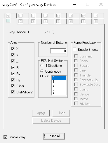
You set up vJoy (image below) one time. This completes your vJoy Device setup.
vJoyConf configuring a virtual joystick with 8 axes, 0 buttons, and 0 hat switches.
This is vJoy Device #1 indicated by the light green tab labeled “1”.
Remaining Instructions
The remainder of these instructions include using Joystick Gremlin
to remap your controller inputs to vJoy.
From the Windows Start menu, run Joystick Gremlin (hereafter called JG).
Create a new Profile in JG. From the JG’s menu, choose File->NewProfile .
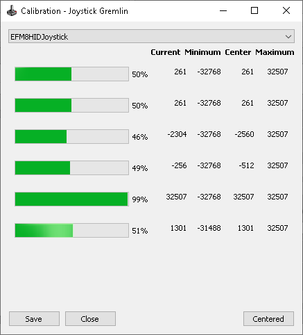
From JG’s menu, choose Tools->Calibration . A calibration window appears.
From top dropdown, choose the name of the controller “EFM…Joystick” (if not already chosen).
Move the active controls: sticks, switches and knob over their full
ranges. The controller will show 6 axes for sticks, “CH6” (knob/flaps),
and “CH5” (gear).
Center the sticks and knob. Click on Centered . Click on Save . Click on Close .
From JG’s menu, choose Tools->InputViewer .
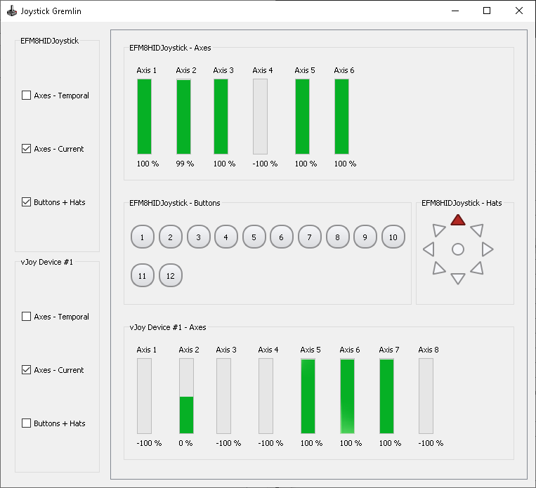
A new window appears (hereafter called JG-viewer). Make it tall as shown below.
In the JG-viewer window, for the EFM…Joystick, check the two boxes: Axes-Current and Buttons+Hats .
For the vJoy Device #1 , check the box:
Axes-Current . FS One will only use vJoy axes.
Move the sticks, knob, and switches
to see that your inputs are being seen by JG.
The vJoy Device #1 axes will not move because you have yet to define the remapping.
See image below.
The particular Detrum controller used in this guide presents an odd
relationship between the Detrum controls and the responding buttons in
Windows. On the Detrum controller, there are only two switches that
respond to Windows buttons, yet those two controls affect 12 Windows
buttons and the Windows Hat. This aspect of the controller is
encountered with the “8 Ch” setup.
JG-viewer
JG input/output viewer showing the axes and buttons for the Detrum controller and vJoy Device.
JG’s top row has tabs for USB controllers, your keyboard, and the vJoyDevice#1 that you created. Generally, the USB controllers are the
inputs to the output that is the virtual joystick vJoyDevice#1
which is used by FS One. The keyboard appears, but it will not
be used here. Other USB controllers will appear if you have others
plugged into your computer. Disconnect any extraneous USB controllers
for this setup.
Tip
When you are finished remapping, follow these steps to use the controller:
In Joystick Gremlin, click the gamepad icon to change it from black to green so that Joystick Gremlin
is Activated. Use JG’s
Tools->InputViewer to confirm that your inputs are going to the vJoy Device joystick
as you expect.
When running FS One, select the vJoy Device virtual joystick that you created.
Do not select the EFM…Joystick.
Before running FS One, it is recommended that you run the Windows Game Controller gadget
to see that vJoy Device is indeed active, responding to your controller inputs.
Each section below remaps a single control (or controls) to one axis for FS One, starting with Ailerons.
First, you move a control to select an input.
It will gray highlight on the left side of JG’s main window.
Then you will define where that control is mapped using the right side of JG main window.
Then you can test each axis mapping with the JG-viewer window to see that it is correct.
Remap the Detrum Controller Axes to vJoy Axes: 4 Ch
This section begins the instructions for making a “4 Ch” setup whereby
only the joysticks are mapped. See table above.
To create your remapping to the standard axes order for FS One,
these steps are performed in JG’s main window.
To start, the JG gamepad icon should be black (not green).
If it is green, click on it.
In JG’s main window, click on the tab: EFM...Joystick .
The left side of the window lists the Detrum’s axes and buttons.
The last moved axis or button will be highlighted gray.
The right side shows what each axis and button does (what will define the remapping).
This right side is initially blank.
The left side’s labels for the axes (e.g., X Axis, and so on) are
the Windows terminology for joystick axes and buttons and not meaningful to FS One.
Yet, the left side names will be used in the instructions here.
Map the Aileron Stick to vJoy Axis 8
First you may need to move the sticks around to ‘wake-up’ the main
JG window. It can go into a “sleep” mode.
Again, the last moved axis or button should highlight gray as you move each control input.
Move the aileron stick (conventionally, for Mode 2, the right stick, horizontally).
In JG, the left side’s highlight jumps to XAxis .
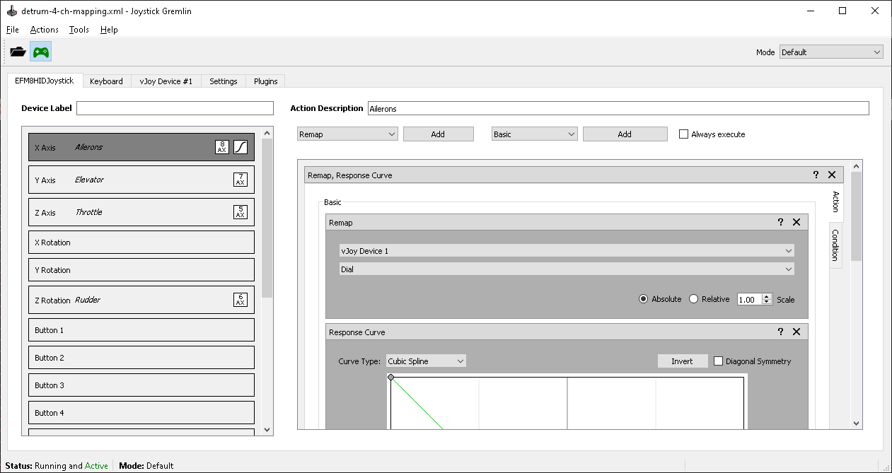
On the right side, into Action Description type “Ailerons”.
On the right side, next to the first dropdown (it will have Remap selected), click Add .
Inside the gray Remap box, change the lower dropdown from XAxis to Dial (vJoy Axis 8).
Below the Remap box, change the dropdown Remap to ResponseCurve . Click Add .
Within the Response Curve box, click on Invert to reverse the axis.
See image below. Click to enlarge.
Test your mapping:
At top left, click the JG gamepad icon (“Activate”) to change it from black to green.
Move the aileron stick.
Now JG-viewer’s vJoy Axis 8 reacts to that movement.
Your first axis remapping is complete.
Click the JG gamepad icon to make it black again.
Click to make it green to review your mapping at any time.
(This screen shot below also shows results of the remaining “4 Ch” instructions. Click for full size.)
Map the Elevator Stick to vJoy Axis 7
Move the elevator stick. The left side’s highlight jumps to YRotation .
On the right side, into Action Description type “Elevator”.
On the right side, next to Remap , click Add .
Inside the gray Remap box, change the lower dropdown to Slider (vJoy Axis 7).
Map the Rudder Stick to vJoy Axis 6
Move the rudder stick. The left side’s highlight jumps to XAxis .
On the right side, into Action Description type “Rudder”.
On the right side, next to Remap, click Add .
Inside the gray Remap box, change the lower dropdown to ZRotation (vJoy Axis 6).
Map the Throttle Stick to vJoy Axis 5
Move the throttle stick. The left side’s highlight jumps to YAxis .
On the right side, into Action Description type “Throttle”.
On the right side, next to Remap , click Add .
Inside the gray Remap box, change the lower dropdown to YRotation (vJoy Axis 5).
This completes the “4 Ch” setup and only uses the joysticks. You could
stop here if you want to test out your controller in FS One
before adding more channel remapping.
Save Your Work
From the menu, File->SaveProfileAs and give it a name, e.g. My-Detrum-4-Ch.xml .
After you have saved it once, you can File->SaveProfile at any time, of course.
Activate and Test
When the JG gamepad icon is green, the JG-viewer window should show vJoy
axes 5/6/7/8 reacting to your Detrum controls defined above. When the
sticks are pushed into the lower left corner, the axes should appear
as shown below. Axes 1/2/3/4 will be in the middle and not move.
If your controller is different and an axis is reversed, then add a ResponseCurve->Invert to
that axis, save, and test.
JG-viewer
JG input/output viewer showing the axes and buttons for the Detrum controller and vJoy Device.
(4 Ch setup)
Remap the Detrum Controller Axes to vJoy Axes: 6 Ch
(adding two more axes)
To the “4 Ch” above, continue and add gear and flaps to make the “6 Ch” setup.
See table above.
Begin by saving your file using File->SaveProfileAs
and give it a name, e.g. My-Detrum-6-Ch.xml .
Map the Gear Switch to vJoy Axis 4
Move the top left side 2-position switch labeled “CH5”.
The left side’s highlight jumps to Dial .
On the right side, into Action Description type “Gear”.
On the right side, next to Remap , click Add .
Inside the gray Remap box, change the lower dropdown to XRotation (vJoy Axis 4).
Below the Remap box, change the dropdown Remap to ResponseCurve . Click Add .
Within the Response Curve box, click on Invert to reverse the axis.
When the gear switch is pulled forward (toward you), the gear will retract.
Map the Flap Knob to vJoy Axis 3
Move the flap knob labeled “CH6”. The left side’s highlight jumps to XRotation .
On the right side, into Action Description type “Flaps”.
On the right side, next to Remap , click Add .
Inside the gray Remap box, change the lower dropdown to ZAxis (vJoy Axis 3).
When the flap knob is turned fully CCW, the flaps will be retracted.
(This screen shot below also shows results of the “6 Ch” instructions. Click for full size.)
Activate and Test
When the JG gamepad icon is green, the JG-viewer window should show vJoy
axes 3/4/5/6/7/8 reacting to your Detrum controls defined above. When the
sticks are pushed into the lower left corner, the vJoy axes 5/6/7/8 should appear
as shown below. When the flap knob is fully CCW (flaps up) and the gear switch is pushed away (gear down),
the vJoy axes 3/4 will be all the way down.
Axes 1/2 will be in the middle and not move.
If your controller is different and an axis is reversed, then add a ResponseCurve->Invert to
that axis, save, and test.
JG-viewer
JG input/output viewer showing the axes and buttons for the Detrum controller and vJoy Device.
(6 Ch setup)
Remap the Detrum Controller Axes to vJoy Axes: 8 Ch
(adding two more axes using buttons)
The remaining two functions are resets and flight modes. Both require
3-position switches. Yet the Detrum only has one 3-position switch
available. It will be use for flight modes. The keyboard will be used
for resets.
Examining the bahavior of the “CH8” 3-position switch shows it
to be unlike a normal switch that triggers a button press in the Window
Game Controller gadget. The switch changes many buttons states at once.
Normally (e.g. as with the InterLink DX simulator controller) a
3-position switch will control two buttons. Nevertheless, the three
switch states are shown below. The top graphic is with the switch in
the high position. Middle graphic is middle switch position, and bottom
is low switch position. While it is unusual, it is usable for the
purpose needed.
Detrum button states for 3-position switch in high, middle, and low
positions. (Your Detrum controller may be different.)
Map the Flight Modes Switch to vJoy Axis 1
The mapping of the “CH8” switch state to vJoy Axis 1 (Flight Modes) will
be constructed to work as follows. For the switch in the high position,
button 7 is Pressed (it turns red in graphic above and is otherwise
off). In that case, the value for vJoy Axis 1 will be set to 1. When
that button is Released (switch moved off of the high position), the
value for vJoy Axis 1 will be set to 0. Next, for the switch in the low
position, button 12 is Released (it turns off, from being red in other
two conditions). Thus, when button 12 is Released, the value for vJoy
Axis 1 will be set to -1. When that button is Pressed (when the
switch is moved off of the low position), the value for vJoy Axis 1 will
be set to 0. Thus with this combination of mapping (transition through
the states), the values for vJoy Axis 1 will be 1/0/-1 with the switch
positions being high/middle/low. Thus, the “CH8” switch that controls
two selected Windows Game Controller buttons (7 and 12) is turned into a
vJoy axis to be read by FS One as the Flight Modes axis. The
settings in JG are below. The process is described step-by-step.
Move the top left 3-position switch back and forth a few times.
This switch is labeled “CH8”. Push the switch up.
In JG, the left side’s highlight jumps to Button7 .
If it is not Button7, move the switch up and click on
Button7 to highlight it on the left side. Note that with the
Detrum triggering myriad buttons (for whatever purpose is unknown), the
left side of JG will auto-select to the
last fired Windows button which may not be Button7. Hence, manually
select it if necessary.
On the right side, into Action Description type “Flight Modes”.
On the right side, change the dropdown from Remap to Macro . Click Add .
Inside the newly added gray Macro box:
In the column of icons, click the top icon.
Inside the right side’s Action Settings do the following:
Change the dropdown from Pause to vJoy .
Below the new dropdown vJoyDevice1 , change the blank dropdown to XAxis (vJoy Axis 1).
Leave the Absolute button checked, not the Relative one.
Arrow up to the value: 1.000 .
At right, click on the sideways tab Condition .
Change the Apply conditions to dropdown to Container .
At right, change the dropdown from KeyboardCondition to ActionCondition . Click Add .
In the new Action Condition box, leave the dropdown as Pressed .
Back to the main top level (still on right side panel), the dropdown should still read as Macro . Click Add to add another macro.
A new Macro box appears below the first Macro box. Scroll down.
Inside the second Macro:
In the column of icons, click the top icon.
Inside the right side’s Action Settings do the following:
Change the dropdown from Pause to vJoy .
Below the new dropdown vJoyDevice1 , change the blank dropdown to XAxis (vJoy Axis 1).
Leave the Absolute button checked, not the Relative one.
Leave the value as: 0.000 .
At right, click on the sideways tab Condition .
Change the Apply conditions to dropdown to Container .
At right, change the dropdown from KeyboardCondition to ActionCondition . Click Add .
In the new Action Condition box, change the dropdown from Pressed to Released .
Move the same top left 3-position switch (“CH8”) down.|br|
The left side’s highlight jumps to Button12 .
If it is not Button12, manually select it as before.
On the right side, into Action Description type “Flight Modes”.
On the right side, change the dropdown from Remap to Macro . Click Add .
Inside the newly added gray Macro box:
In the column of icons, click the top icon.
Inside the right side’s Action Settings do the following:
Change the dropdown from Pause to vJoy .
Below the new dropdown vJoyDevice1 , change the blank dropdown to XAxis (vJoy Axis 1).
Leave the Absolute button checked, not the Relative one.
Arrow down to the value: -1.000 .
At right, click on the sideways tab Condition .
Change the Apply conditions to dropdown to Container .
At right, change the dropdown from KeyboardCondition to ActionCondition . Click Add .
In the new Action Condition box, change the dropdown from Pressed to Released .
Back to the main top level (still on right side panel), the dropdown should still read as Macro . Click Add to add another macro.
A new Macro box appears below the first Macro box. Scroll down.
Inside the second Macro:
In the column of icons, click the top icon.
Inside the right side’s Action Settings do the following:
Change the dropdown from Pause to vJoy .
Below the new dropdown vJoyDevice1 , change the blank dropdown to XAxis (vJoy Axis 1).
Leave the Absolute button checked, not the Relative one.
Leave the value as: 0.000 .
At right, click on the sideways tab Condition .
Change the Apply conditions to dropdown to Container .
At right, change the dropdown from KeyboardCondition to ActionCondition . Click Add .
In the new Action Condition box, leave the dropdown as Pressed .
When the flight mode switch is pushed down, it will be
the “low” rates flight mode
(and pushed away, “high” rates).
However,
the specific descriptor when running FS One does depend on the
airplane in FS one.
Activate and Test
When the JG gamepad icon is green, the JG-viewer window should show vJoy
axes 1/3/4/5/6/7/8 reacting to your Detrum controls defined above. When the
sticks are pushed into the lower left corner, the vJoy axes 5/6/7/8 should appear
as shown below. When the flap knob is fully CCW (flaps up) and the gear switch is pushed away (gear down),
the vJoy axes 3/4 will be all the way down.
When the flight mode switch is pushed down, vJoy axis 1 will be all the
way down. Axis 2 will be in the middle and not move.
If your controller is different and an axis is reversed, then add a ResponseCurve->Invert to
that axis, save, and test.
JG-viewer
JG input/output viewer showing the axes and buttons for the Detrum controller and vJoy Device.
(8 Ch setup)
This screen shot below also shows results of the “8 Ch” instructions. Click for full size.
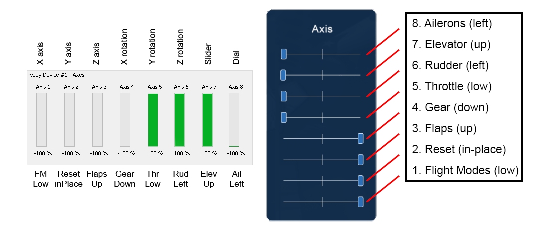
In summary, your controller inputs (whether you used the 4, 6, or 8 Ch setup)
should match the standard axes order
below which also shows the axis directions (via showing the result of
full stick, knob, and switch throws in the specific directions).
The mapping order, generally, was discussed here.
Axes that you did not map will be in the middle.
In this diagram, the “Axis 1” for vJoy is “1. Flight Modes” (“FM”) for FS One, etc.
When you finish this guide, return back to the last part of Getting Started: Part I to continue your
setup and run FS One.
Click image to enlarge.
Standard axes order in FS One with sliders at full deflections for the controls indicated.